Background
No matter the scale, flight planning has always been key to any successful aerial photogrammetry/remote sensing project. The rules for UAS are no different. Additionally, a successful flight plan is characterized by knowing the specifications of the camera/sensor and having a UAS that is capable of flying with that sensor mounted.
Part of the planning process involves defining a number of specifications for the desired end-product before going into the field. Some basic considerations include:
- Image resolution: How much detail is desired? A smaller ground sample distance (GSD or pixel resolution) will have a higher resolution compared to a larger one. The flying height and focal length of a cameras sensor determine the pixel resolution.
- Image overlap and sidelap: Image overlap and sidelap are essential for the establishment of tie points that orient the images and create the 3D model. Traditional standards call for 60% overlap and 30% sidelap, however, UAS acquisition usually requires higher variations of both.
- Sun angle and weather: Reducing the amount of shadows is very important when capturing aerial imagery. Having the sun at it’s peak height in the sky minimizes shadows and allows the sensor to receive as much light as possible. Wind also plays an important factor. How powerful is your UAS? How powerful of wind gusts can it handle and still maintain a level position?
So you are ready to make a successful flight and have all of the flight planning figured out. The next question, however, is how geographically accurate should it be? If one is only interested in a product that is marginally accurate, say within 1-5 meters, than the GPS from the flight log file or camera would be sufficient.
For survey grade accuracy however, having ground control points measured from a professional land surveyor is necessary. Control points are the most accurate way to ground truth any georeferenced product.
Software

For flight planning, I use Mission Planner. It is free to download and very easy to use. I have an ideal ground station by combining this software and the supplied telemetry antennas that came with the 3DR IRIS. With a few simple clicks, Mission Planner is able to display flight data in real-time through a series of interchangeable gauges.
The Flight Plan tool allows the user to plan varies autonomous missions and tasks by establishing GPS waypoints. For my project, I used the survey (grid) tool. Within minutes I had my area of interest (AOI) polygon, entered my camera specifications (the iPhone 5s’ focal length is 4.12 mm) and set my overlap and sidelap (70 and 60 percent).
On top of flight planning, Mission Planner also acts as the control station for the IRIS. By using the supplied telemetry kit, my laptop was able to send and receive data in real-time to the copter. A log file was also recorded storing all of the flight parameters.
Imagery Acquisition
 The desired pixel resolution for this project was 1 cm. Considering the highest resolution from traditional manned aircraft missions averages between 1-3 inches, resolution to this degree from a consumer grade product like an iPhone is quite remarkable.
During the flight, the camera shutter was activated using an intervalometer feature from an 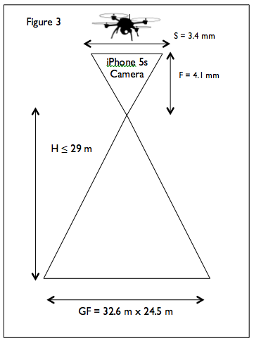 app called CameraSharp. The app allows you to set the seconds interval at which you wish to snap photos. For this project, I went with one photo every second. 70% overlap was achieved by setting the flight speed to 7 m/sec and activating the camera shutter every second (Table 2). Ten flight lines ensured 40% side lap based on the 32 m x 24 m ground footprint (Figures 7-8).
 Ground Control
Coordinate System: UTM Zone 10N Horizontal Datum: WGS-84
Vertical Coordinate System: NAVD 1988
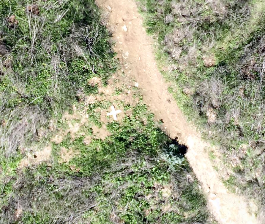
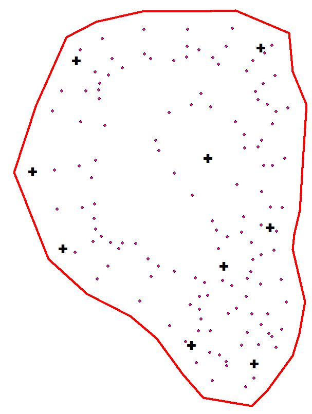
Nine GCPs (black crosses) were surveyed for accurate georeferencing by using RTK GPS. 132 checkpoints (pink circles) were also surveyed for reference data (Figure 6). Horizontal and vertical accuracies of the RTK GPS were 2 cm.
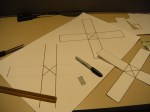
Aerial targets were fabricated using some poster board that were cut 5 cm wide at the edges. Nine targets were placed around the site providing a sufficient ground truth throughout. The targets were measured during image processing.